All latches have two inputs: data and enable/disable.
And typically Q and ![]() outputs.
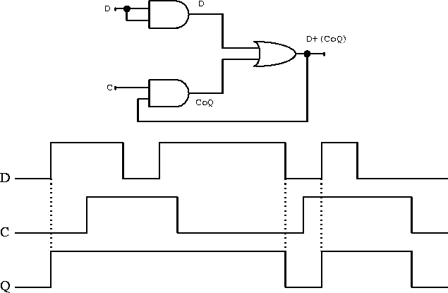
A ones-catching latch can be built as shown in
figure 7.17.
outputs.
A ones-catching latch can be built as shown in
figure 7.17.

Figure 7.17: An AND-OR gate used as a ``ones catching''
latch and its timing diagram.
When the control input C is false, the output Q follows the input D, but when the control input goes true, the output latches true as soon as D goes true and then stays there independent of further changes in D.
One of the most useful latches is known as the transparent latch or D-type latch. The transparent latch is like the ones-catching latch but the input D is frozen when the latch is disabled. The operation of this latch is the same as that of the statically triggered D flip-flop discussed below.
Narippawaj Ngernvijit