Next: Problems Up: Circuit Applications of Ordinary Previous: Diode Gate

Diode Protection

An important use of diodes is to suppress the voltage surge present when an inductive load is switched out of a circuit - inductive surge suppression. With inductors it is not possible to turn off the current suddenly since the inductor will try to keep the current flowing when the switch is opened. A diode in a DC circuit or back-to-back zener diodes in an AC circuit can be used to shunt the inductor and prevent it from conducting.

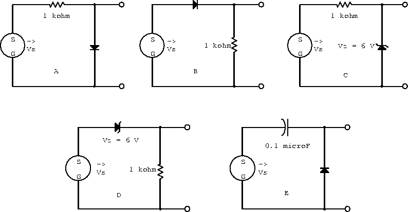
Example: For each circuit in figure 4.14 sketch the output voltage as a function of time if  V. Assume that the circuit elements are ideal.

 
Figure 4.14:  Circuits with a single ideal diode.

The forward and reverse biased approximations for the circuit in figure 4.14a are shown in figure 4.15 and the output voltage is sketched in figure 4.20a.
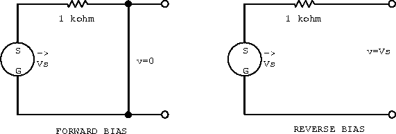
 
Figure 4.15:  Single diode circuit a).

The forward and reverse biased approximations for the circuit in figure 4.14b are shown in figure 4.16 and the output voltage is sketched in figure 4.20b.
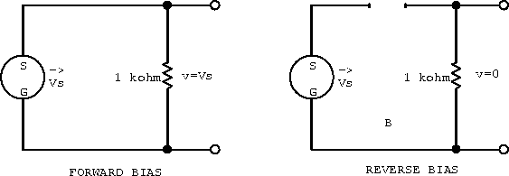
 
Figure 4.16:  Single diode circuit b).

The forward and reverse biased approximations for the circuit in figure 4.14c are shown in figure 4.17 and the output voltage is sketched in figure 4.20c.
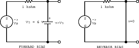
 
Figure 4.17:  Single diode circuit c).

The forward and reverse biased approximations for the circuit in figure 4.14d are shown in figure 4.18 and the output voltage is sketched in figure 4.20d.
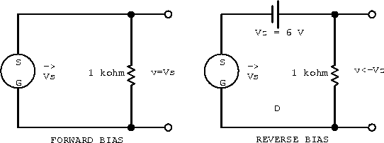
 
Figure 4.18:  Single diode circuit d).

The forward and reverse biased approximations for the circuit in figure 4.14e are shown in figure 4.20 and the output voltage is sketched in figure 4.20e.
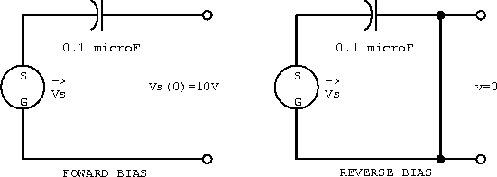
 
Figure 4.19:  Single diode circuit e).
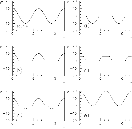
 
Figure 4.20:  Sketch of the output voltage as a function of time.
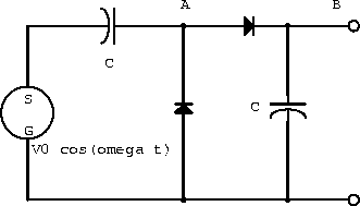
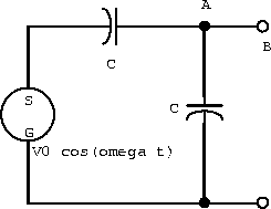
Example: Assuming that the diodes in the circuit below are ideal, write expressions for the voltage at points A and B.

 
Figure 4.21: A circuit with two ideal diodes.

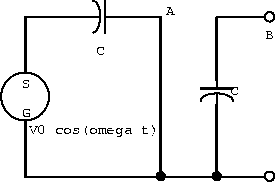
Consider when the current flows in the clockwise direction (figure 4.22). in the steady state because the charge just builds (it has nowhere to ``drain" to).

 
Figure 4.22:  Current clockwise.

Consider when the current flows in the anti-clockwise direction (figure 4.23). , since this is just the output terminal of the voltage source. in the steady state, again since the charge cannot go anywhere.

 
Figure 4.23:  Current anti-clockwise.

Thus by superposition


Next: Problems Up: Circuit Applications of Ordinary Previous: Diode Gate

Narippawaj Ngernvijit